


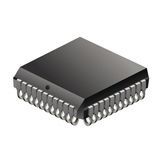
4-Bit/8-Bit MCU
The AT89C51CC03 is a member of the family of 8-bit microcontrollers dedicated to CAN network applications. In X2 mode a maximum external clock rate of 20 MHz reaches a 300 ns cycle time. Besides the full CAN controller AT89C51CC03 provides 64K Bytes of Flash memory including In-System Programming (ISP), 2K Bytes Boot Flash Memory, 2K Bytes EEPROM and 2048 byte ERAM. Primary attention is paid to the reduction of the electro-magnetic emission of AT89C51CC03.
- 80C51 Core Architecture
- 256 Bytes of On-chip RAM
- 2048 Bytes of On-chip ERAM
- 64K Bytes of On-chip Flash Memory
- Data Retention: 10 Years at 85°C
- Read/Write Cycle: 100K
- 2K Bytes of On-chip Flash for Boot loader
- 2K Bytes of On-chip EEPROM Read/Write Cycle: 100K
- Integrated Power Monitor (POR: PFD) To Supervise Internal Power Supply
- 14-sources 4-level Interrupts
- Three 16-bit Timers/Counters
- Full Duplex UART Compatible 80C51
- High-speed Architecture
- Five Ports: 32 + 4 Digital I/O Lines
- Five-channel 16-bit PCA with
- PWM (8-bit)
- High-speed Output
- Timer and Edge Capture
- Double Data Pointer
- 21-bit WatchDog Timer (7 Programmable Bits)
- A 10-bit Resolution Analog to Digital Converter (ADC) with 8 Multiplexed Inputs
- SPI Interface, (PLCC52 and VPFP64 packages only)
- Full CAN Controller
- Fully Compliant with CAN Rev 2.0A and 2.0B
- Optimized Structure for Communication Management (Via SFR)
- 15 Independent Message Objects
- Each Message Object Programmable on Transmission or Reception
- Individual Tag and Mask Filters up to 29-bit Identifier/Channel
- 8-byte Cyclic Data Register (FIFO)/Message Object
- 16-bit Status and Control Register/Message Object
- 16-bit Time-Stamping Register/Message Object
- CAN Specification 2.0 Part A or 2.0 Part B Programmable for Each Message Object
- Access to Message Object Control and Data Registers Via SFR
- Programmable Reception Buffer Length Up To 15 Message Objects
- Priority Management of Reception of Hits on Several Message Objects at the Same Time (Basic CAN Feature)
- Priority Management for Transmission
- Message Object Overrun Interrupt
- Supports
- Time Triggered Communication
- Auto baud and Listening Mode
- Programmable Automatic Reply Mode
- 1-Mbit/s Maximum Transfer Rate at 8 MHz Crystal Frequency in X2 Mode
- Readable Error Counters
- Programmable Link to On-chip Timer for Time Stamping and Network Synchronization
- Independent Baud Rate Prescaler
- Data, Remote, Error and Overload Frame Handling
- On-chip Emulation Logic (Enhanced Hook System)
- Power Saving Modes
- Idle Mode
- Power-down Mode
- Power Supply: 3 volts to 5.5 volts
- Temperature Range: Industrial (-40°Cto +85°C), Automotive (-40°C to +125°C)
- Packages: VQFP44, PLCC44, VQFP64, PLCC52
Характеристики
| Бренд | Microchip |
|---|---|
| Special F | CAN Controller |
| Interface Type | CAN/SPI/UART |
| Device Core | 80C51 |
| Number Of | 37 |
| Screening Level | Industrial |
| Рабочая температура | -40 to 85 °C |
| Number Of | 3 |
| Ram Size | 2.25 KB |
| Program M | 64 KB |
| Maximum O | 5.5 V |
| Watchdog | 1 |
| Program M | Flash |
| Instructi | CISC |
| Minimum O | 3 V |
| On Chip Adc | 8-chx10-bit |
| Maximum Speed | 40 MHz |
| Operating | 3.3, 5 V |
| Schedule B | 8542390000 |
| HTSN | 8542310001 |
| Страна происхождения | Китай |
| Data Memo | 2 KB |
| Data Bus Width | 8 Bit |
| Family | AT89C51CC03 |
| Упаковка | Tube |
| Maximum P | 1000 mW |
| Analog Co | 2 |
| Maximum E | 64 KB |
SKU: AT89C51CC03CA-SLRUM